
crane runway beam
Fatigue Analysis of Crane Runway Beam
Compared with other large equipment, steel crane runway beams work under extremely complex load stress conditions. It turns out that the cyclic fluctuating loads from the point of view of the resistance of the crane runway girders lead to the formation of numerous cracks and damage. This load has a significant effect on the life of the web in the plate I cross-section of the crane runway beam. The complex state of stress is determined by the overall bending causing normal and shear stresses and eccentric loading of crane wheels. The stress component due to overall bending is identified as type I stress, while the stress component due to crane wheel load is referred to as type II stress. This combination of stresses reduces the fatigue strength of the web.
1. Map of relative stress ranges according to stresses in crane runway girders and railway bridges.
It is widely recognized in the industry as an important factor leading to fatigue cracks. The stress intensity of the crane runway beam is much larger than that of the railway bridge in the variation range spectrum.
For cranes in lifting classes HC1-HC4, and for girders of railway bridges with a span length of 60 m, the crane takes into account the working time of the working day, the ratio of the load lifted to the safe load during the working day, and the frequency of lifting.
The second multiparametric factor that contributes to the reduction of fatigue strength of steel structures is welding. The base material is remelted in high-gradient thermal heat, mixed with additional material and cooled rapidly, resulting in significant changes in the crystal structure in the specific heat-affected zone of the weld contact. In addition, internal welding stresses and microcracks remain in the heat-affected zone. These factors reduce the dependence of fatigue strength on static tensile strength (i.e. material type).
High levels of fatigue interaction and the negative effects of welding lead to the failure of welded crane runway beams known as plate girders within a relatively short time after they start operating. Macroscopic fatigue cracks appeared after two years of operation, and the crack frequency intensified between the 6th and 12th years of operation, as shown in Fig. 2, which depicts the relationship between the relative number of investigated beams and the time to crack. This rapid response to fatigue loading is due to the stress concentration around the microcracks and the embrittlement of the steel under cyclic loading conditions. The effective concentration factor for crack locations increases with increasing structural life.
2. The web in the runway beam of the welded plate crane
Based on the results of failure investigations on used crane rails and the results of model-based experimental tests and theoretical analysis, it can be concluded that the component most prone to fatigue cracking of crane rail girders is the web. The increased sensitivity of the web relative to the beam flange is due to the following effects:
(1)Cyclic variable mobile drive wheel loads for crane bridges
(2)Reticular respiration in the intercostal plates
(3)The torque on the flange of the beam is produced by the eccentric crane wheel load relative to the vertical axis of the web, and the eccentric horizontal impact of the wheel on the rail head
3. The cause of fatigue stress
In the variable repetitive stress region at the structural details considered, that is, the joint between the web and the flange in the associated beam, the whole process can be divided into incubation period and expansion period, and in the high stress range of stress changes, the incubation period is relatively short and the propagation period is relatively long. However, in the low stress range of stress change, the crack latency is relatively long and the propagation period is relatively short. When the stress is maintained near the stable fatigue limit, the crack initiation period can be regarded as the failure period of the component. Under the influence of the principal shear stress, the first grain on the surface of the element begins to produce fatigue cracks. It is 45° diagonal to the direction (at an Angle) of the principal shear stress. After several adjacent grains are reached, the crack changes to the direction at right angles to the first principal normal stress and begins to propagate. Fatigue crack initiation is caused by shear stress because in this case, the durability of the material is lower than the normal stress.
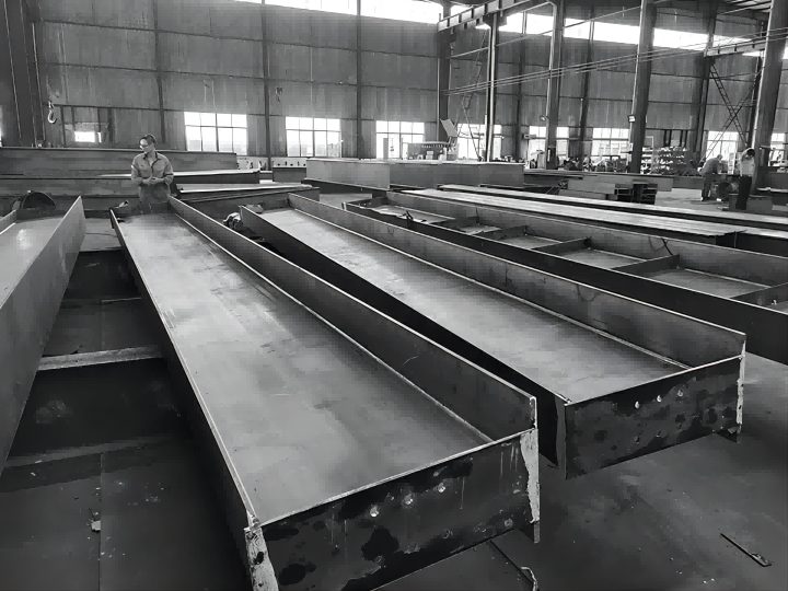
In GloryRail’s H-beam processing workshop, the design and production of steel structures for crane runway beam are some of our important products. GloryRail is committed to reducing the cost and improving the efficiency of the track system. The steel structure production line has undertaken this task. This service greatly reduces the cost investment of customers in track installation. Compared with For traditional steel structure manufacturers, the special crane beam for the rail system achieves the goals of lower cost, more reliable quality, and a higher degree of fit.


